
Circuit Components:
- ATmega8 controller
- PCB board
- IR sensors -4
- LED’s-12(4-red,4-green,4-yellow)
- 12v Battery or adaptor
- Serial cable
- Connecting wires
Density Based Traffic Light Control System Circuit Design:
This circuit consists of 4 IR sensors, atmega8 microcontroller, 4 traffic lights.
IR transmitter looks like an LED. This IR transmitter always emits IR rays from it. The operating voltage of this IR transmitter is 2 to 3v. These IR (infra red) rays are invisible to the human eye. But we can view these IR rays through camera.
IR receiver receives IR rays that are transmitted by IR transmitter. Normally IR receiver has high resistance in order of mega ohms, when it is receiving IR rays the resistance is very low. The operating voltage of IR receiver also 2 to 3V.
We have to place these IR pair in such a way that when we place an obstacle in front of this IR pair, IR receiver should be able to receive the IR rays. When we give the power, the transmitted IR rays hit the object and reflect back to the IR receiver.
Instead of traffic lights, you can use LEDs (RED, GREEN, YELLOW). In normal traffic system, you have to glow the LEDs on time basis. If the traffic density is high on any particular path, then glows green LED of that particular path and glows the red LEDs for remaining paths.
In normal traffic system, we allow the traffic for a time delay of 1 minute for each path.
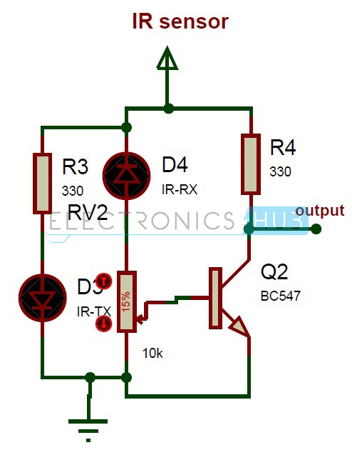
IR Sensor Circuit
The above figure shows the IR sensor circuit. Here 330 ohm resistor is used to drop the voltage otherwise IR transmitter may get damaged. To vary the obstacle sensing distance, we have used a potentiometer. We have taken the ouput from transistor collector. This sensor gives the digital output.
No comments:
Post a Comment